BY LETTER
Aerovac foam
Technology > Application > Construction
Technology > Application > Everydaytech
Technology > Application > Materials Technology
Technology > Application > Everydaytech
Technology > Application > Materials Technology
Aerostatic Vacuum-Pneumatic Cell Foam |
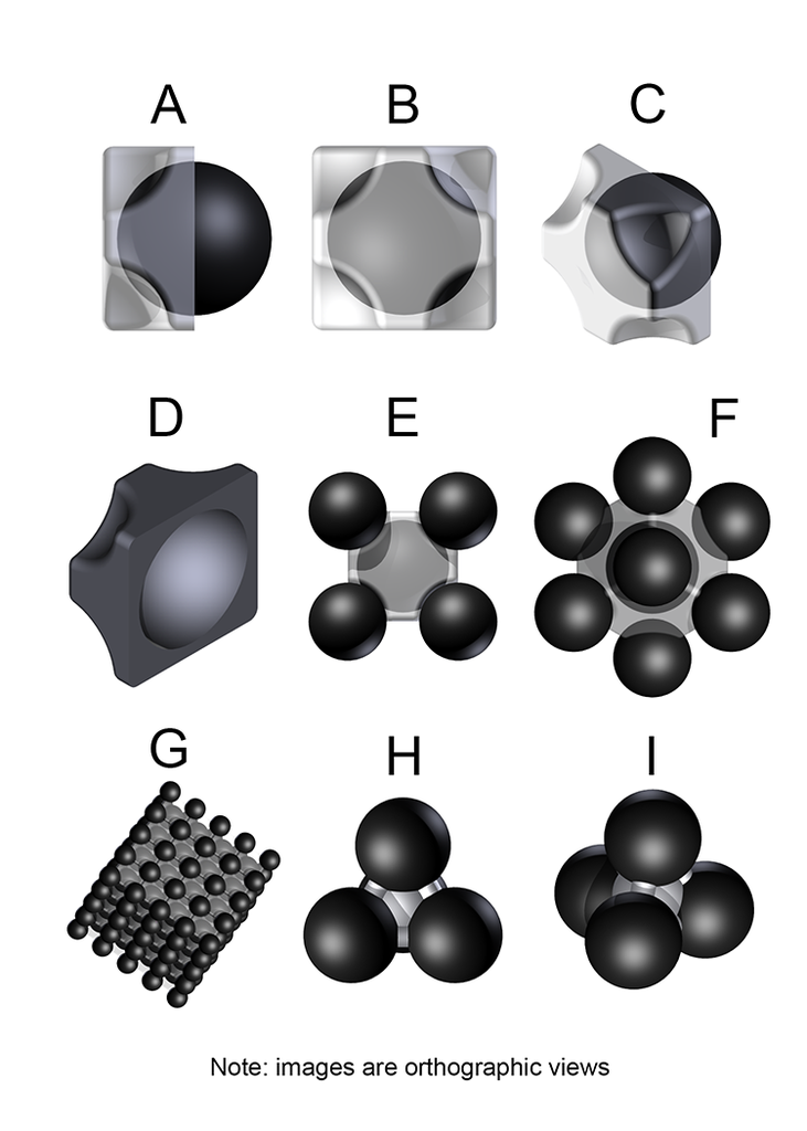 Image from Johnny Yesterday |
A. Side-view of one half of a two-part pneumatic cell with the internal vacuum cell clearly visible on one side.
B. End-view of one half of a two-part pneumatic cell with the internal vacuum cell partially visible through the material of the pneumatic cell.
C. Isometric view of one half of a two-part pneumatic cell with the internal vacuum cell visible.
D. Isometric view of one half of a two-part pneumatic cell with the internal concave surface visible.
E. End-view of a pneumatic cell with the internal vacuum cell partially visible, and four of the eight vertex-centered vacuum cells clearly visible.
F. Isometric view of a pneumatic cell with the internal vacuum cell barely visible, and seven of the eight vertex-centered vacuum cells clearly visible.
G. View of a cube of aerovac foam.
H. Side-view of a minimal Type 2 lattice unit.
I. Elevated-view of a minimal Type 2 lattice unit.
Aerostatic Vacuum-Pneumatic Cell Foam(aerovac foam, vac-foam etc.)
Aerovac foam is a technology used to create lighter-than-air vehicles, structures, and so forth that is based in vacuum aerostat technology, but that offers a substantial increase in catastrophic-failure resistance against the baseline architecture.A basic vacuum aerostat is a thin-shell vessel in the shape of a sphere or ellipsoid. The wall of the vessel is composed of three layers: inner and outer solid layers of an equal thickness, and a substantially thicker core layer between them that has a honeycomb, reticulated foam, or space-frame structure. Using this architecture, and constructing it using materials with sufficiently high elastic moduli and tensile and compressive strengths, an aerostatic structure with a sufficient safety factor against buckling collapse can be produced. Silicon carbide, boron carbide, diamond-like carbon and beryllium have adequate properties; as such, vacuum aerostats are within high-end manufacturing capability of Middle-tech 1.
Utilizing boron carbide, vacuum aerostats can be given a safety factor of 5.42, or 442% above the minimum that is required to resist buckling collapse against a standard pressure of 100 kPa. High-tech nanofactured materials such as poly-adamantine composites improve the safety factor, but no monolithic structure is impervious to buckling or being ruptured. The solution is to subdivide; instead of a monolithic vacuum aerostat, the volume of space that it would occupy is instead tessellated by numerous smaller iterations. However, this solution in and of itself is not sufficient. Because of their surface curvature, close-packed spheres only make contact with one another at points on their surfaces. These points are locations of concentrated stress, and concentrated stress can easily lead to buckling collapse. The stress between vacuum spheres must be spread more evenly over their surface area. This is primarily accomplished in two different, but similar, ways.
The first method envelops, and suspends, each vacuum cell inside the core of a pneumatic cell sandwich. The pneumatic cells serve to isolate each vacuum cell from coming into direct contact with one another, providing a cushion between them that spreads the load evenly across their surfaces. These pneumatic cells can come in various shapes. The most efficient design is composed of cubical cells with spherically-truncated vertices. The vacuum aerostats are arranged in the structure in a body-centered cubic lattice; larger diameter vac spheres are located at the center-point of each unit cell, and slightly smaller vac-cells2 are located at the eight corner (vertex) points. For illustrative purpose, the pneumatic cells are translucent in many of the images. In actuality, the outermost pneumatic cells in a mass of aerovac foam are opaque or mirrored with aluminum to provide UV shielding to the vac cells and pneu-cell envelopes, if they are composed of carbon allotropes.
In the second method, the vacuum cells are tessellated in Euclidean-space in a face-centered cubic (fcc), or hexagonal close-packed (hcp) lattice structure. In either sphere-packing geometry, the center of each vacuum cell is located at a vertex of one or more imaginary tetrahedrons. The center of each pneumatic cell is centered on the center of one of the imaginary tetrahedrons.
The pneumatic cells are filled with a gas that is plentiful in the atmosphere, but one that has a lower molar mass than the atmospheric composition as a whole. For example, in an Earth-like atmosphere the gas would be nitrogen. The pneumatic cell envelope has a low enough mass that the cells are positively buoyant. At Middle-tech level, aramid or carbon fiber are typical materials used for the cells. Vacuum and pneumatic cells in Middle-tech aerovac foam are larger than those produced using High-tech molecular manufacturing technology, because Middle-tech materials do not have sufficient tensile strength to create durable pneu-cell envelopes that are 0.4 µm thick. The vac cells are larger because their size is tied to that of the pneumatic cells, not because of inherent limitations in the materials that constitute them. High-tech pneumatic cells are fashioned from woven penta-graphene or boron nitride nanoribbons. Cell designs exist that can self-repair minor damage like punctures and cuts, and re-inflate using molecular sorting rotor pumps that are embedded in the wall of the cell envelope.
Although lone aerostatic vacuum cells of a diameter much less than 50 cm exist in various applications such as small drones, they are atypical in aerovac foam for several reasons. The square-cube law makes the pneumatic cells grow increasingly materially inefficient at smaller and smaller dimensions, eventually reaching the point where they are negatively buoyant, and thus become a payload that the vacuum cells must lift. Additionally, a 50 cm dia. vac cell that is composed of boron carbide and that has a safety factor of approx. 2.8 under 101 kPa of atmospheric pressure has a lift capacity of approx. 42 grams at an atmospheric density of 1.288 kg/m^3.
Often used in vacuum dirigibles and other large-scale buoyant vehicles and structures.
1/ A. Akhmeteli and A. Gavrilin. 'Layered Shell Vacuum Balloons.' Patent application number: US 20070001053A1
2/ The relative diameter of the larger cells as compared to the smaller is expressed by the ratio 20:17.
Related Articles
Appears in Topics
Development Notes
Text by Johnny Yesterday
Initially published on 08 April 2015.
Initially published on 08 April 2015.